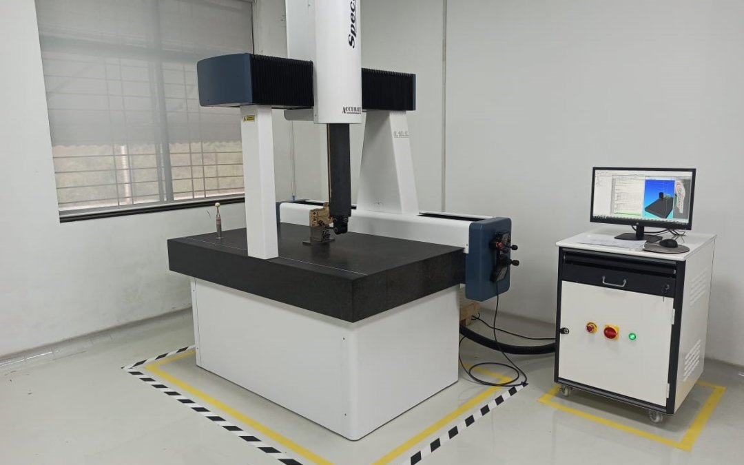
Make – Accurate gauging systems Pvt Ltd, INDIA.
Model – Spectra
Operation – CNC
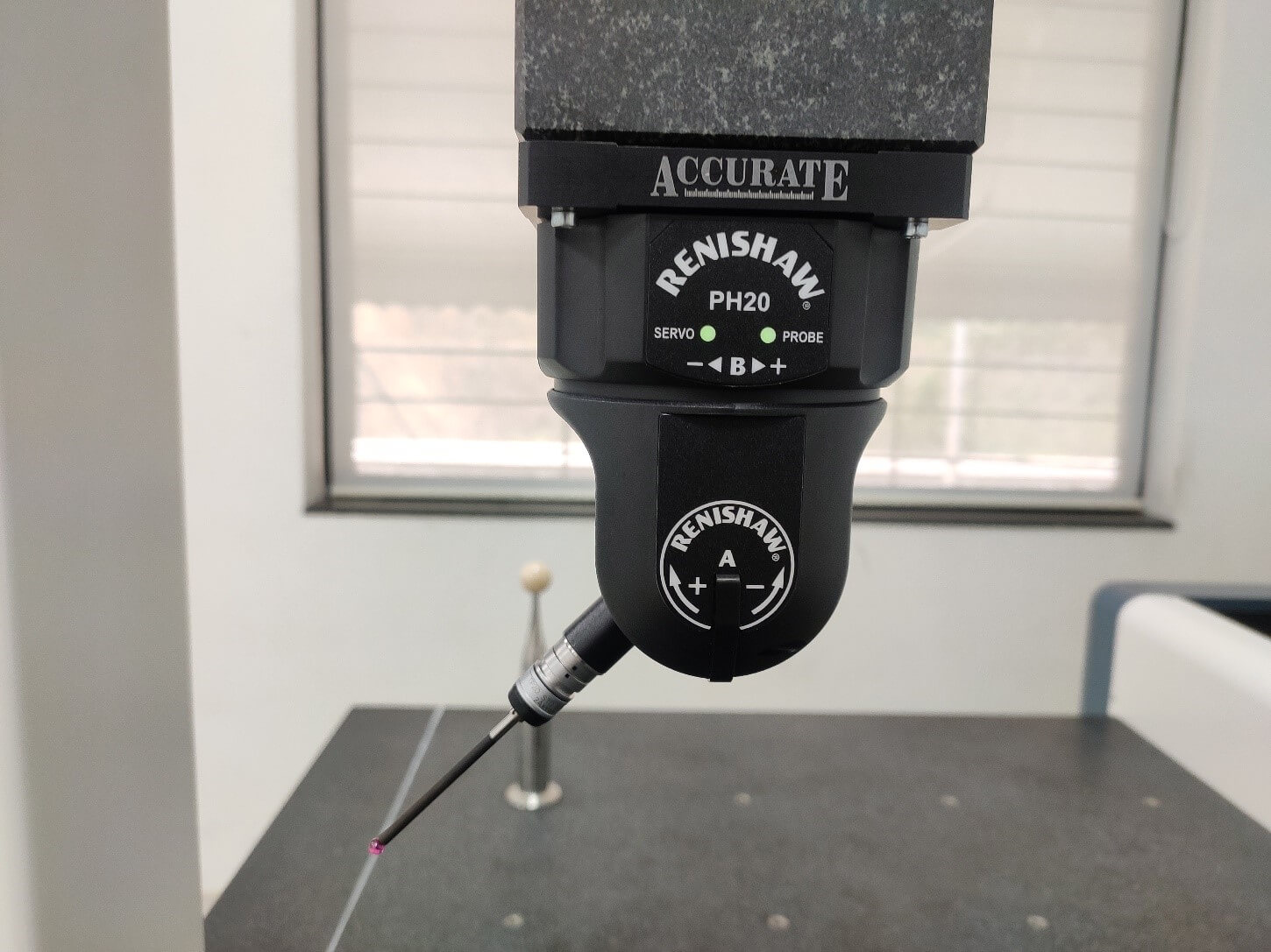
Renishaw Probing System – PH20MT 5-Axis Touch Trigger system, Integral TP20 Probe Module.
Measuring Range – X 600mm, Y 1000mm & Z 500mm.
Full Operating System – CAD Comparison, Graphical Presentation, Input CAD file format & Neutral IGS.
What is a Coordinate Measuring Machine?
A coordinate measuring machine uses a very sensitive electronic probe to measure a series of discrete points from the geometry of a solid part. These measurements are used to confirm the part’s conformance to specifications according to the manufacturing drawing.
What are the Components of a CMM?
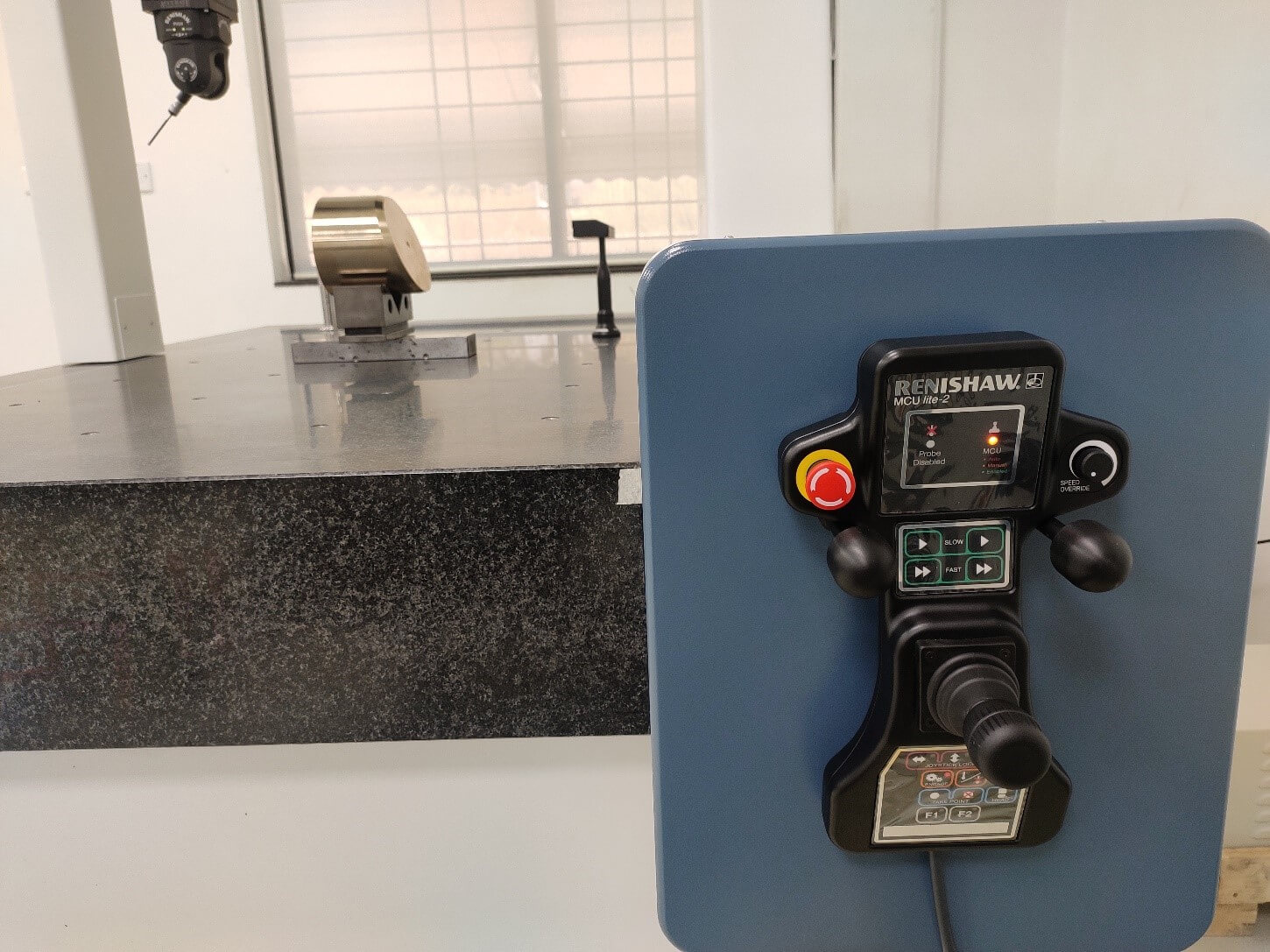
Parts to be measured are securely mounted on a solid table, usually made of granite, that has been ground flat. The probes, which come in different sizes and types, are mounted on a spring-loaded stylus and this stylus is connected to a gantry that moves in an X-Y-Z coordinate plane.
The probe and stylus are also able to rotate independently to access different part features. All the motions of the gantry and probe can be controlled manually via a joystick or programmed automatically. This makes the CMM a true computer-numerical-controlled machine.
What is a Probe?
Probes that make use of physical contact, rather than optical light or lasers, rely on spherical tips made from ruby or another rigid and stable material that will not change size due to temperature fluctuations. The probe and stylus are connected to exquisitely sensitive electronics that detect even the slightest deviation in electrical resistance coming from the probe. Each time the spherical tip contacts a solid object and is forced to deflect it generates an electrical signal which is recorded in the computer. Any number of points can be measured depending on the requirements of the part.
How is This Data Used?
The purpose of collecting these points is two-fold. Individual points are used to confirm measurements of actual parts against a customer’s CAD file data or Manufacturing drawing for the purpose of quality assurance.
Or these points can be collected to create a “point cloud” outlining the shape of the part.
This is useful when a single sample of a part is used as the foundation of a CAD program to make more parts, such as with CNC machining.
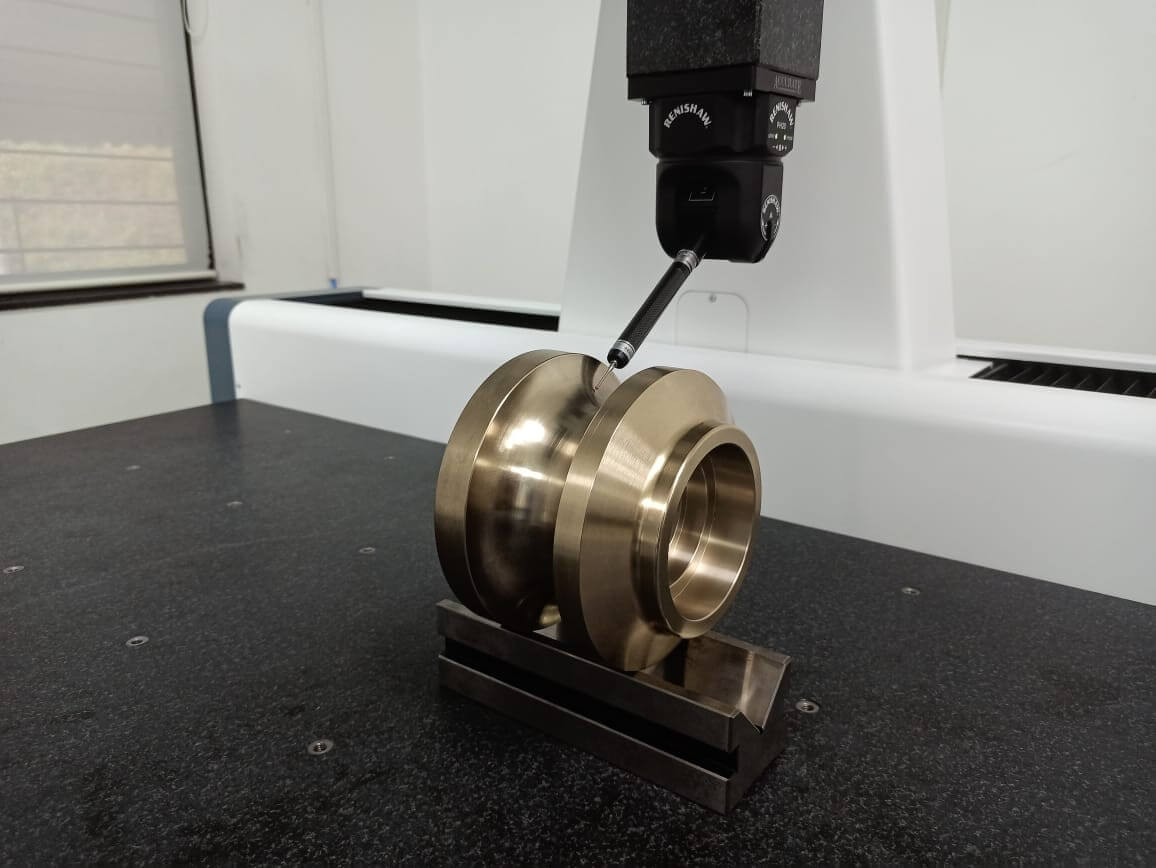
CMMs can be particularly useful when measuring points inside of holes/bores, geometrical dimensions like flatness, roundness, squareness, parallelism, cylindricity, etc. These recessed areas can be difficult or impossible to measure with normal measuring instruments like Vernier Caliper, micrometer, or 2D measuring gauge, or even with optical systems because the light tends to reflect and bounce around inside the feature, causing interference and inaccuracy.
Are There Limitations to the CMM?
All touch probes make physical contact with an object to take a reading. The size of the probe tip must therefore be suitable for the features it is intended to measure. A tip that is too large will be unable to resolve fine features smaller than itself. Also, the tip must be very clean, at the microscopic level, to ensure that no foreign contaminants get between the tip and the workpiece.
Very soft and pliable rubbers or elastomers might be so yielding under the touch of the probe that the surface deflects slightly, causing an errant reading.
How Reliable is the CMM?
The reliability of the CMM is dependent upon a very rigid physical frame that does not distort over time or due to environmental conditions. Our Accurate make Spectra bridge-type CMM, using a Renishaw PH20MT probe, is guaranteed to maintain its accuracy for 5 years without requiring adjustment or calibration due to its robustness and reliability of its design.
How the test protocol looks which is generated from CMM?
Below is the sample of the test protocol which we can directly generate through CMM after inspection of any part/item.
